
flexible PCB boards tested for durability
Flexible PCBs open up new design possibilities for a variety of electronic devices. Their ability to bend, fold and twist allows them to fit into tight spaces where rigid PCBs cannot. This flexibility also protects the circuit board from mechanical failure by absorbing shocks and vibrations, making them ideal for use in harsh environments. The durability of flexible circuit boards is a key factor in their popularity among aerospace, automotive, consumer electronics and medical device manufacturers.
To ensure that flex PCBs meet quality standards, manufacturers must implement rigorous testing and quality control processes. These include visual inspection, dimensional testing, electrical testing, flex testing and environmental and reliability testing. By following these guidelines, manufacturers can avoid the costly errors and defects that could cause a flex circuit board to fail in its intended application.
The first step in preparing a flexible pcb board for production is selecting the base material and copper foil thickness that best meets the product’s demands. Then, the board’s circuit design is mapped out using software before it’s transferred to the copper foil by photolithography. The circuit traces are then etched away through chemical etching, leaving behind the designed copper pads and traces. Holes (vias) can be drilled at this stage for electrical connections between layers in multilayer flex PCBs.
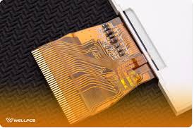
How are flexible PCB boards tested for durability?
Once the bare copper is plated, coverlayers and stiffeners can be applied to the board. Then, the stacked layers are laminated together with adhesive. After lamination, the stack is exposed to UV or IR heat for curing, which strengthens the adhesion and helps the boards resist damage during manufacturing and end-use.
After the flex circuit boards are assembled and soldered, they must undergo rigorous testing to confirm that they’re ready for use. This testing includes a peel test that evaluates the strength and resilience of the PCB’s laminate. It also tests for proper flex and bending and a solder float test that measures how much stress the holes on the board can withstand.
A flex circuit’s conductivity, signal loss and tensile strength are also important factors for durability. To minimize signal loss, FPCs are made with high-quality copper that’s highly conductive and can withstand high temperatures.
To improve conductivity, PCB manufacturers plate flex circuits with high-temperature copper and apply an antireflective finish to reduce light reflectance. These features help minimize signal loss and improve visibility for users.
The flexibility of flex circuits makes them ideal for applications that require frequent bending, twisting and flexing. However, if the flex circuits are subjected to excessive bending, they may develop cracks and breaks that affect its performance and functionality. To prevent this, flex circuits must be tested for bending resistance and tensile strength before they’re used in any application. These tests are conducted by a professional engineer using specific and precise test equipment to ensure that the flex circuits will remain functional and durable when subjected to repeated stress. This enables them to continue working in harsh conditions for the duration of their expected life.